Factory controls
Keep the pack’s activation, firing, and power controls working.

A2ThreeD installation guide
Sound Effects Upgrade for HalloweenCostumes / Fun.com Proton Packs
Install ProtonPal alongside the factory pack electronics to add upgraded sound playback while keeping the original pack controls and optional wand volume control.
Keep the pack’s activation, firing, and power controls working.
Connect one speaker or wire the factory pair in series.
Load replacement WAV files for higher-quality custom sounds.
Before you begin
Turn off the pack and remove the batteries before opening the pack or changing any wiring. Work slowly: the original electronics wiring and terminals are somewhat fragile.
Installation
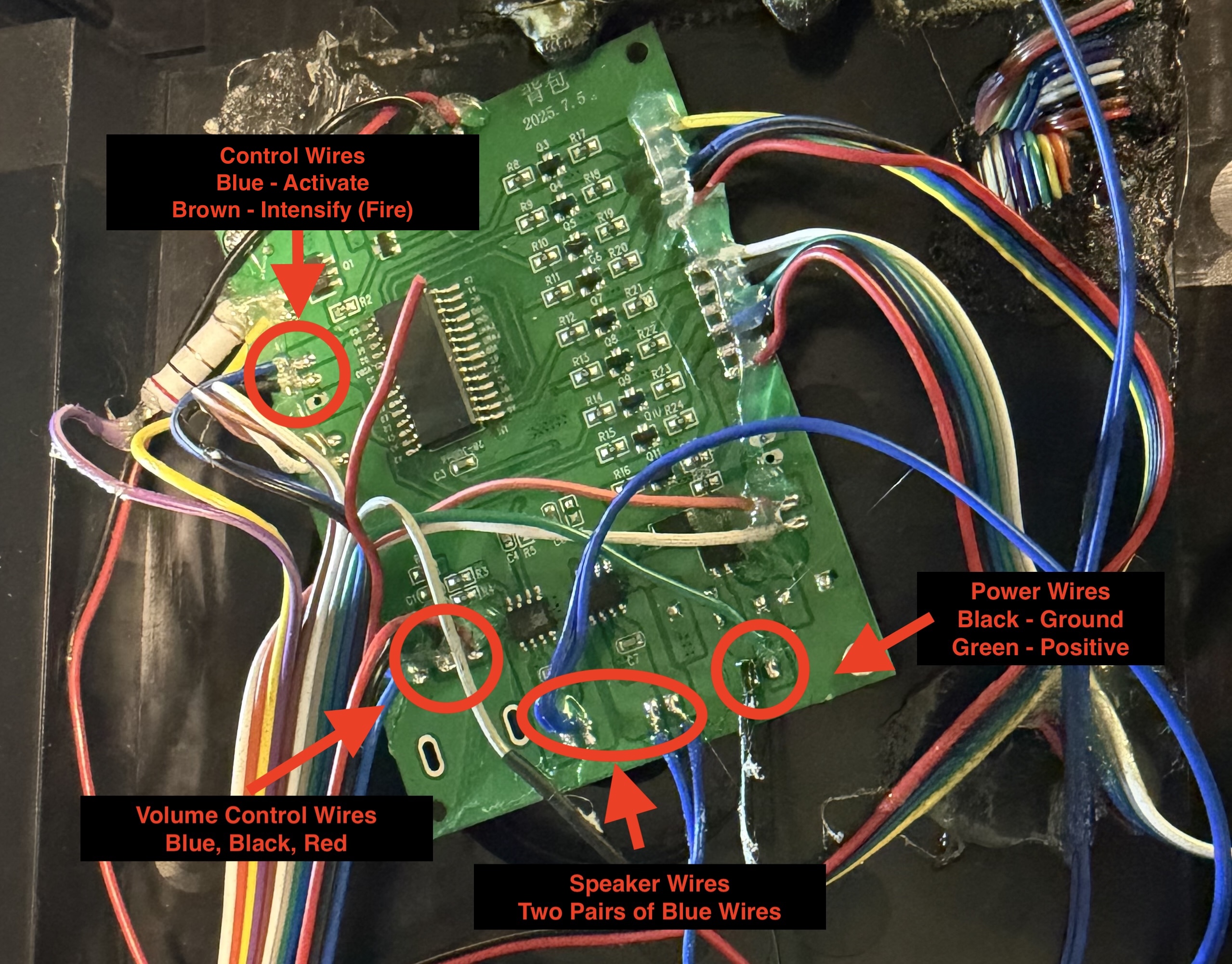
Follow the steps in order and compare each connection with the annotated PCB photo before securing the wiring.
Remove the ALICE frame and the back of the pack, including the motherboard cover, so you can access the internal electronics.
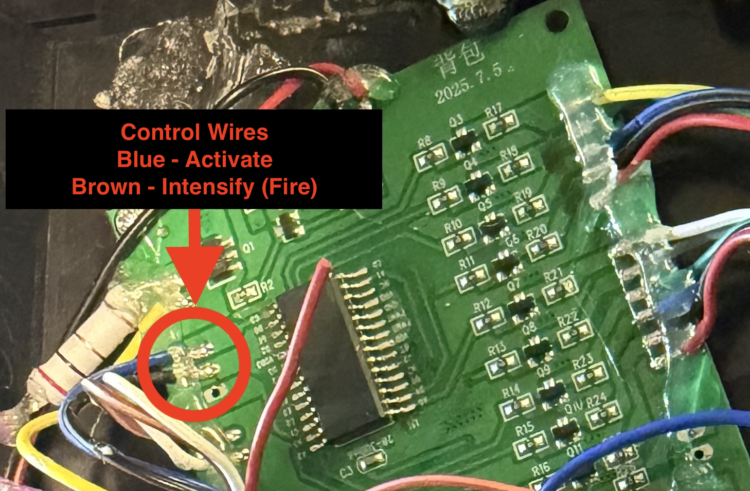
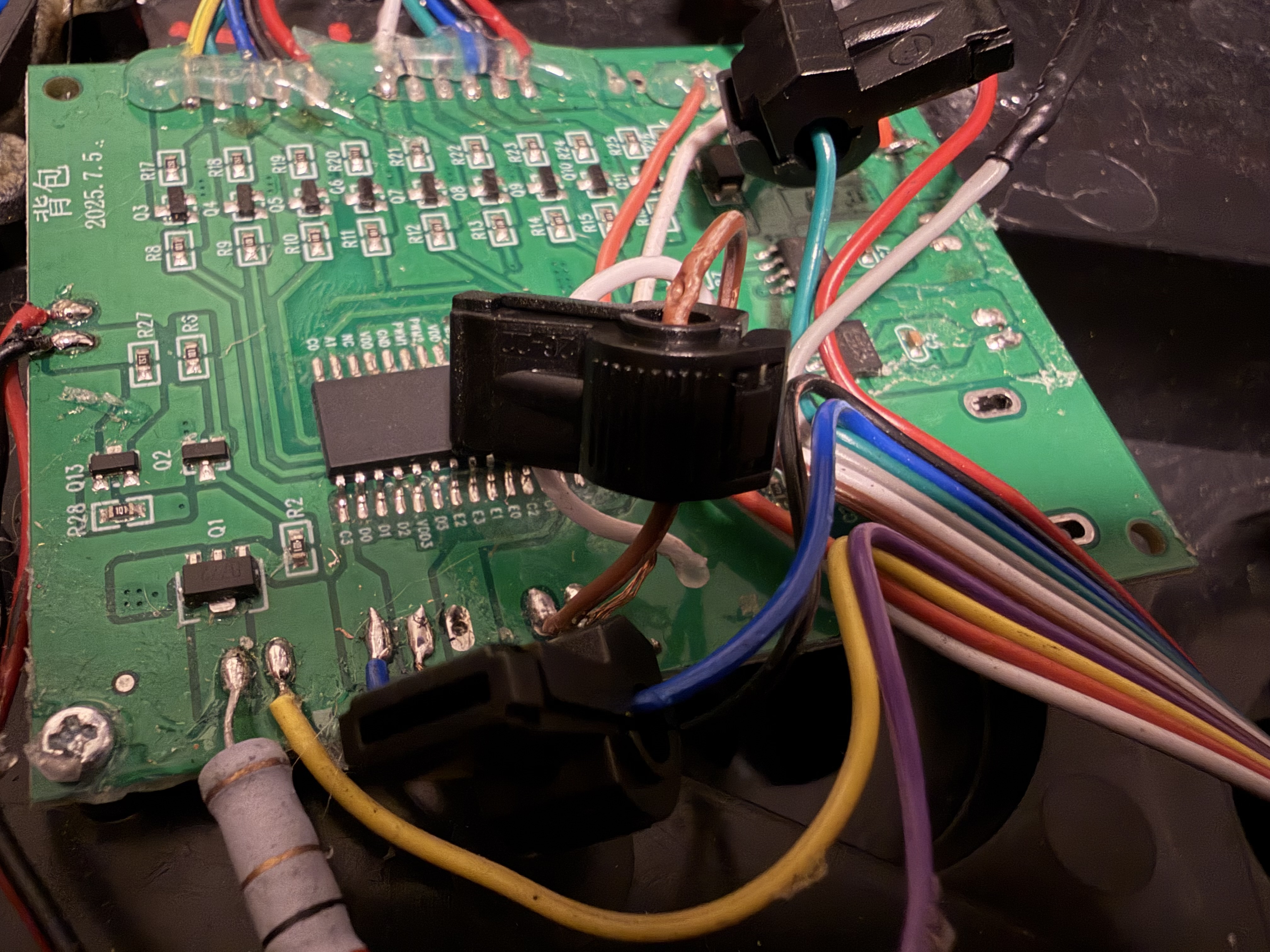
Locate the wiring on the original pack electronics PCB. The annotated photo identifies the control, power, speaker, and volume connections needed for ProtonPal.
Take the two-pin JST-XH cable with the red and black wires from the ProtonPal kit. Slide the wire-tapping connectors over the black and green power wires identified in the photo.
Use pliers to close each tap assembly so it makes a tight connection to the factory wire.
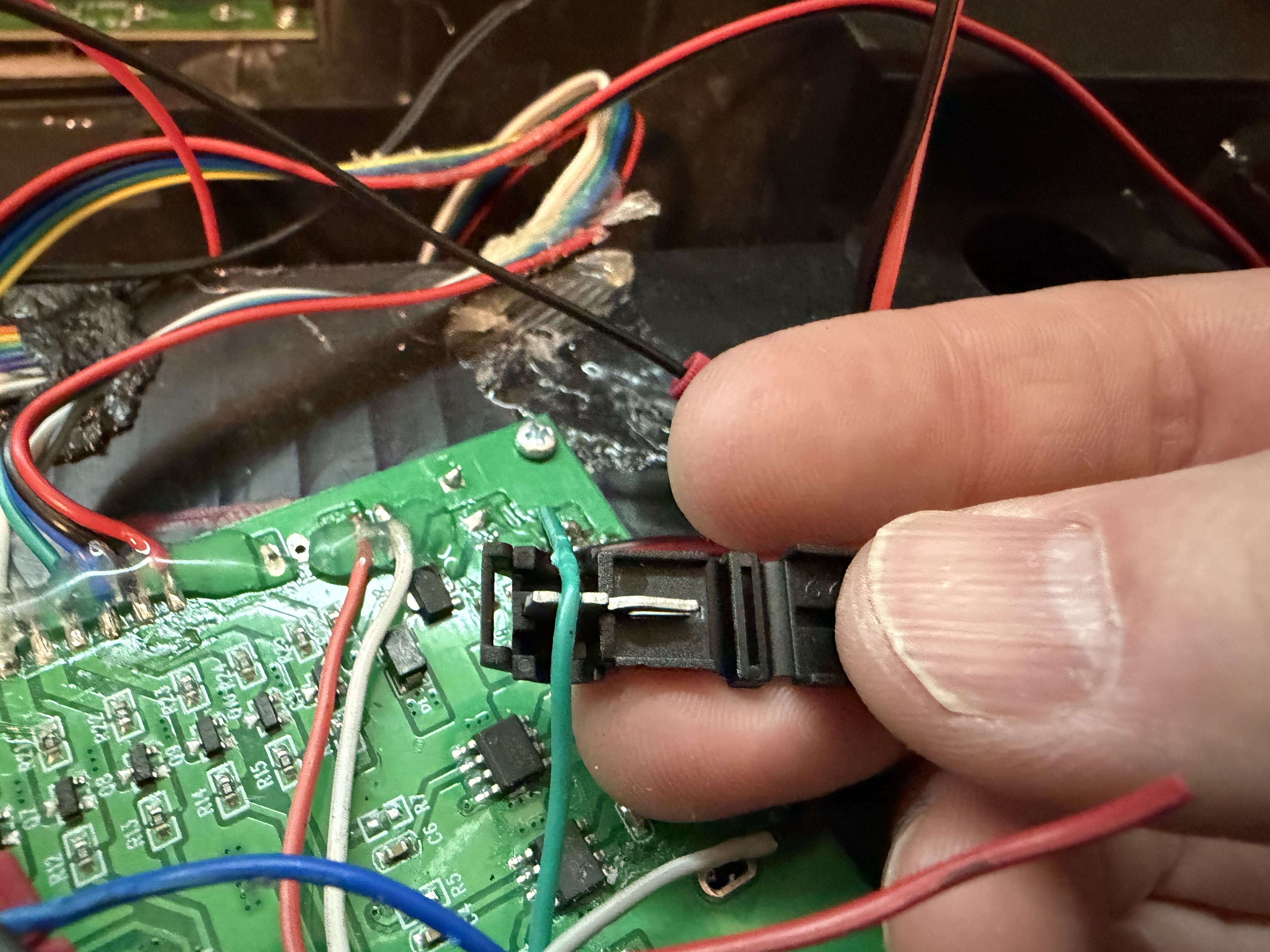
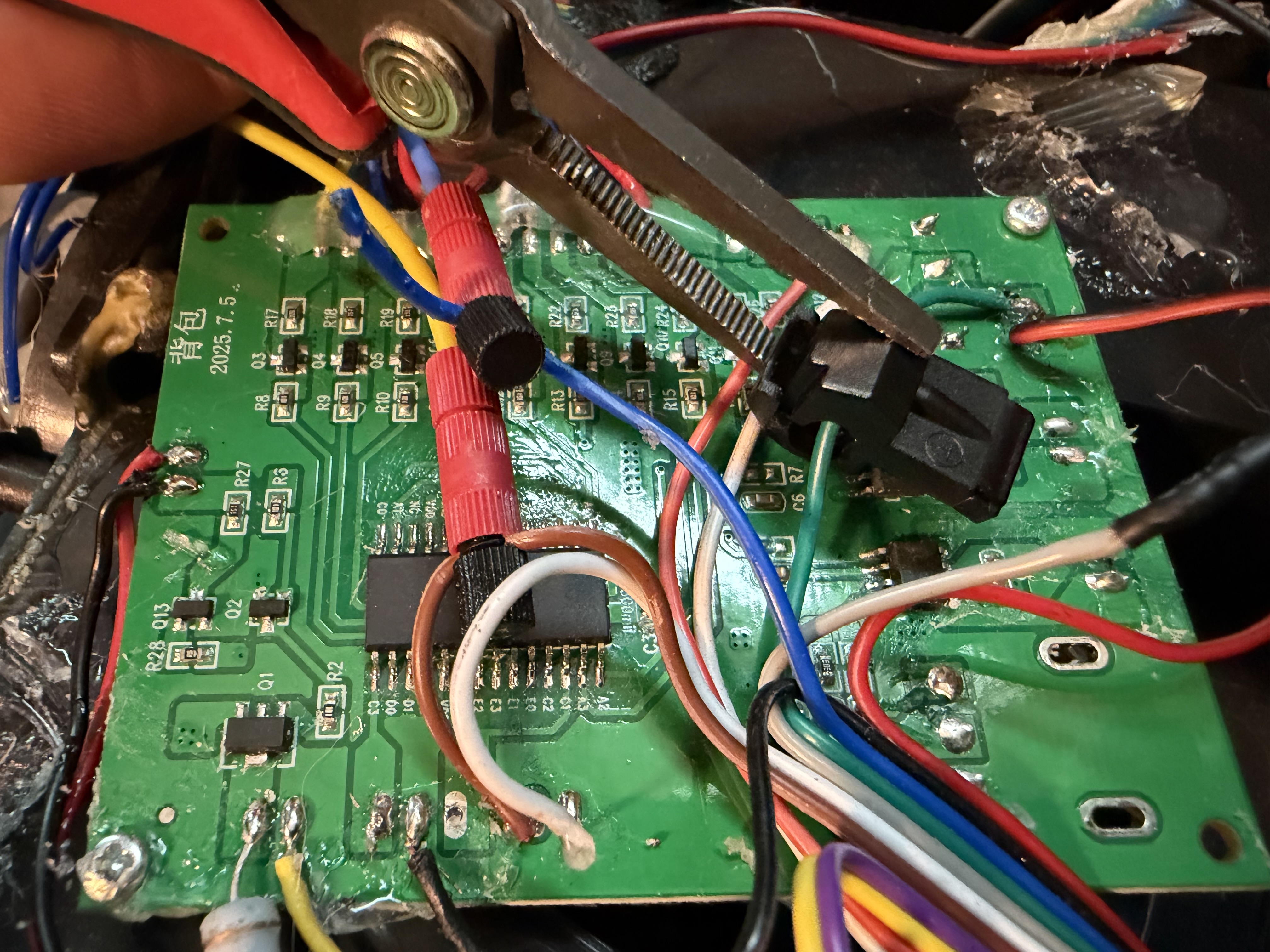
Take the two-pin JST-XH cable with the blue and yellow wires. Locate the two control wires shown in the upper-left area of the annotated photo. The factory wires may be tightly bound, so carefully separate them without pulling on the PCB connections.
Attach the wires with the supplied crimping connectors.
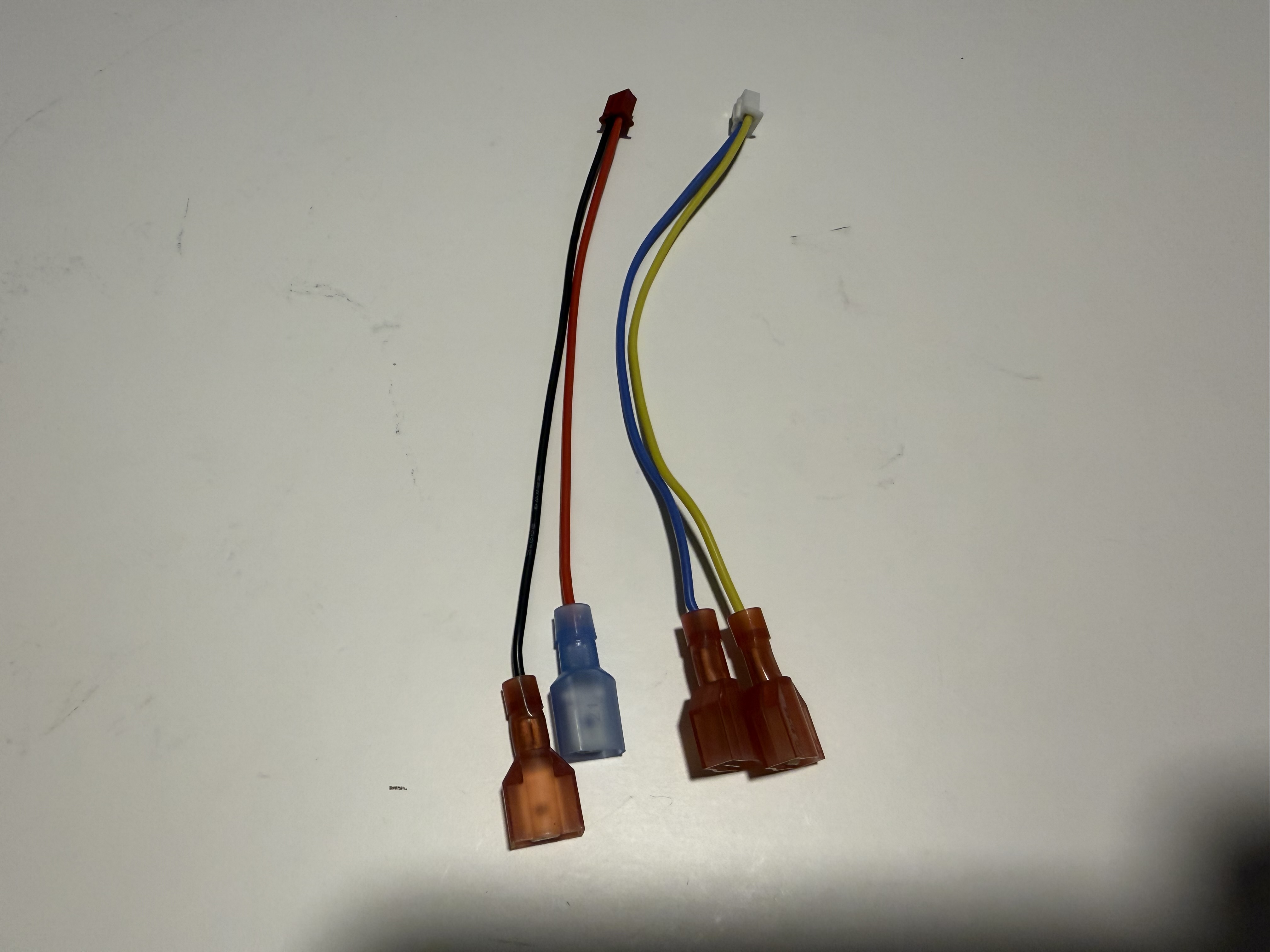
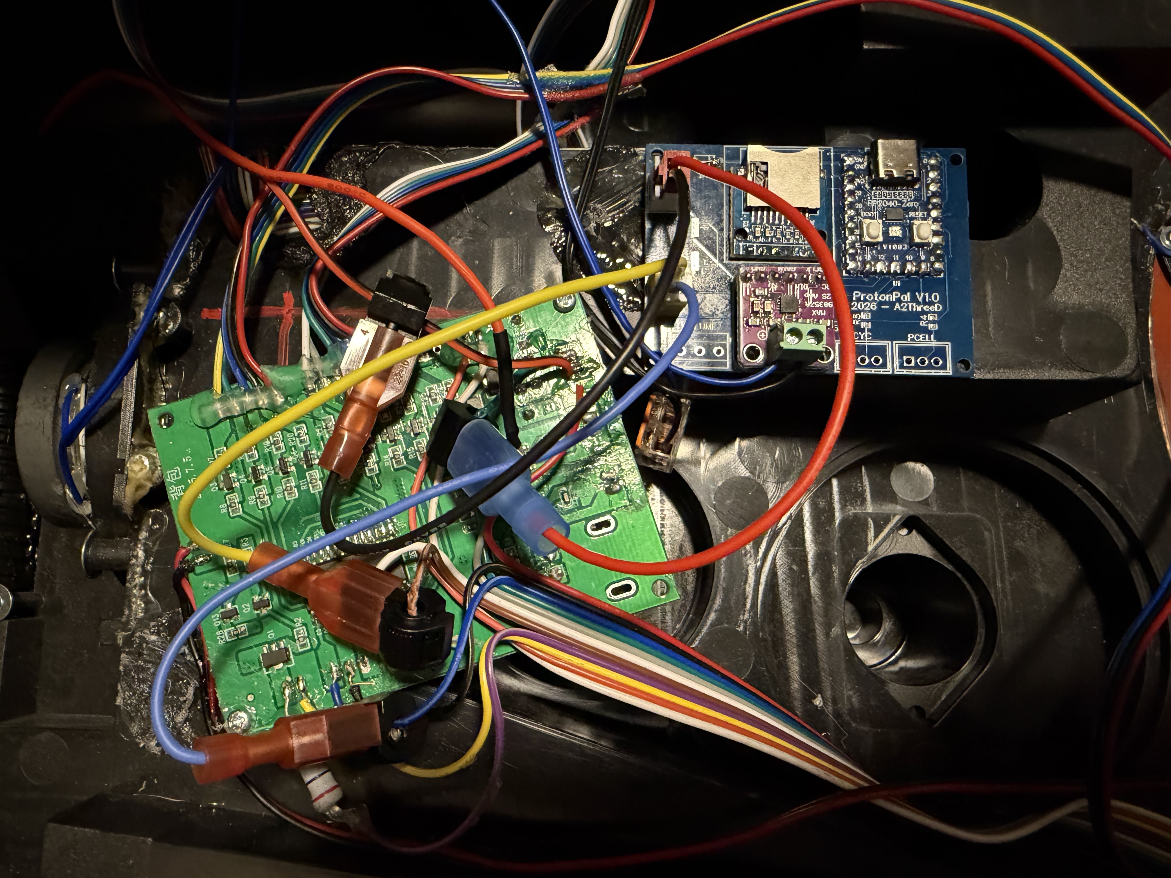
Locate the two JST wiring assemblies with spade terminals. The assembly with the red and black wires plugs into the ProtonPal board’s 5V IN connector. The other assembly plugs into the yellow HC BRD connector on the board.
Attach the spade terminals to the wire taps as shown:
Push the spade terminals firmly into the taps, but support the taps while doing so to avoid breaking the wiring.
Clip the blue speaker wires from the bottom of the factory PCB, or desolder them. If desoldering, heat the hot glue first so the wires can be removed without stressing the board. If you clipped the wires, strip the ends.
ProtonPal has one speaker amplifier output. Choose one of these options:
Important: Insulate or secure any unused speaker wires so they cannot touch another conductor.
To keep volume control from the factory wand, clip or desolder the three-wire volume-control cable identified in the photo. Strip the wire ends if you clipped them.
Open the three-position screw terminals on ProtonPal with a small flat-head screwdriver if necessary. Insert the wires from left to right in this order:
Tighten each terminal and check that no stray wire strands are exposed.
Install the batteries and test before final installation. Verify power on/off, pack activation on/off, and both firing buttons. Confirm that the sound functions respond correctly.
ProtonPal includes basic lower-quality sounds internally. You can replace them with your own sounds by installing a FAT32-formatted MicroSD card. Use WAV files up to 44 kHz, 16-bit.
bootup.wavPlays when the pack is activatedshutdown.wavPlays when the pack is shut downidlehum.wavLoops while the pack is running / idlingfiring.wavPlays while the fire button is depressedfiretail.wavPlays when the fire button is releasedSecure the ProtonPal board and route the wiring so it cannot move, rub against sharp edges, or be pinched.
After the test is successful, reinstall the back and ALICE frame. Confirm that the battery compartment, wiring, and shell close without issue.